Week 12: Registers and memory elements
🏠 Home · Prev: Week 11 · Next: Week 13
Goal. Group flip-flops into registers, the small fast storage the MCU uses for its working values. The MCU’s RA and RB are registers built exactly this way.
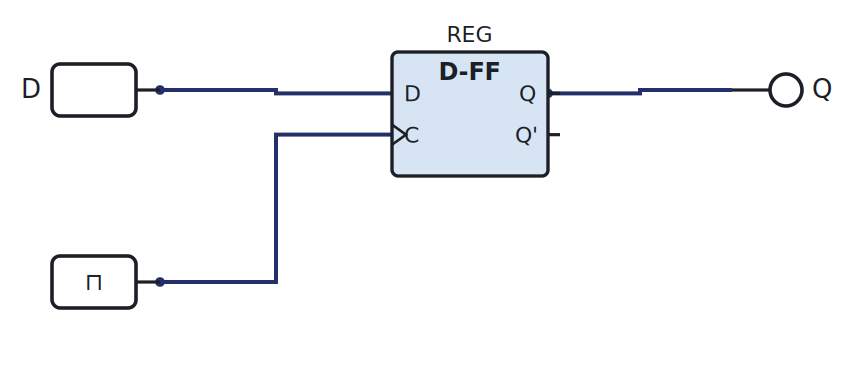
A flip-flop is a 1-bit register
One D flip-flop stores one bit: load it on the clock edge, and it holds that bit until the next edge.
An n-bit register
Put n D flip-flops side by side, all sharing one clock, and you store an n-bit word in one tick. Add a load/enable line (gate the clock or multiplex the input with the current value) so the register only updates when you ask it to. The MCU’s registers A and B are 4-bit registers with exactly this enable.
Shift registers
Chain the flip-flops instead, feeding each output into the next one’s input. On every clock the data shifts one position along the chain.

Serial in, serial out turns one wire into many over several clocks (and back), which is how a few pins drive many outputs. Parallel-load and parallel-out variants exist too.
Mealy and Moore machines
A sequential machine’s outputs can be defined two ways, and these are the two categories you should recognise:
- Moore: outputs depend on the state only. The output changes only after a clock edge, which makes it clean and glitch-free.
- Mealy: outputs depend on the state and the current inputs. It can react one clock sooner, at the cost of following input glitches.
We do not design with formal state-machine diagrams beyond the truth-table method of Week 10; knowing the two categories is enough.
Try it yourself (optional)
Build a 4-bit shift register from D flip-flops, clock it from the Arduino, and watch a single 1 walk along the outputs on the logic analyser. See the Lab Annex.
Check yourself
- How many clocks to load a 4-bit value into a shift register serially? To read it out?
- Sketch how a load/enable line stops a register from updating every clock.
- Is a simple counter a Moore or a Mealy machine?