Week 11: Counters, dividers, and the program counter
🏠 Home · Prev: Week 10 · Next: Week 12
Goal. Use flip-flops to count. A counter is the heart of the microcontroller’s program counter, the register that decides which instruction runs next.
Ripple (asynchronous) counters
The quickest counter to build: clock the first flip-flop, then let each flip-flop’s output clock the next. The count “ripples” up the chain.
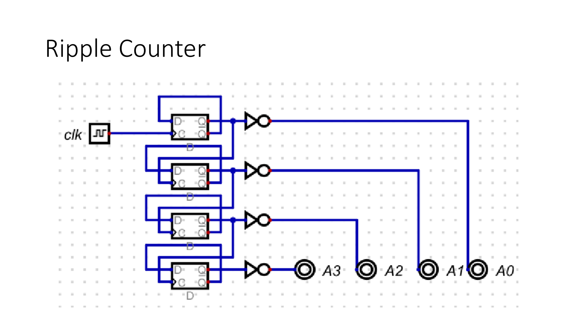
It is simple, but like the ripple-carry adder it has a delay: the top bit only settles after the change has rippled through every stage. For fast or precise timing you use a synchronous counter instead, where every flip-flop shares one clock, designed by the Week 10 method.
Frequency divider
A single D flip-flop with its Q’ fed back to D toggles on every clock edge, so its output is the clock at half the frequency. Chain them and each stage halves again: divide by 2, 4, 8.
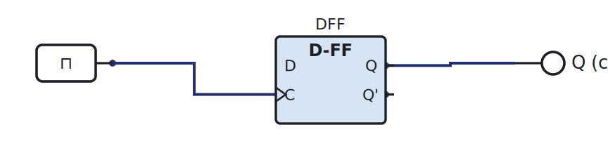
This is also why a ripple counter’s bits are a chain of divided clocks.
BCD counter
A counter that resets after 9 instead of after 15 counts in binary-coded decimal, one decimal digit per 4 bits. Detect the count reaching ten and clear the flip-flops. It is what drives a decimal display.
The program counter
Now the payoff. A program counter (PC) is just a counter whose value is the address of the next instruction. Each clock it increments, the ROM hands back the instruction at that address, and the machine executes it.
When we build the MCU, the PC steps through the program in ROM exactly like this counter steps through its states.
Try it yourself (optional)
Build a divide-by-2 with one flip-flop, watch the output on the logic analyser at half the clock, then chain a second stage. See the Lab Annex.
Check yourself
- How many flip-flops does a counter that reaches 100 need?
- A 1 MHz clock through three divide-by-2 stages gives what frequency?
- Why does a program counter need a way to load a value, not only increment? (Think jumps.)