Week 10: Sequential design, one method
🏠 Home · Prev: Week 9 · Next: Week 11
Goal. Design any sequential circuit with the same truth-table method you already use for combinational logic. No new theory, no excitation tables.
The whole idea
A sequential circuit is just combinational logic plus flip-flops:
- The flip-flop outputs are the present state. Treat them as extra inputs to your combinational logic.
- The flip-flop inputs are the next state. Treat them as extra outputs of your combinational logic.
And because we use D flip-flops, the rule Q_next = D means the next state is the D input.
So you never need an excitation table: whatever you want the next state to be, that is what you
feed to D.
The recipe
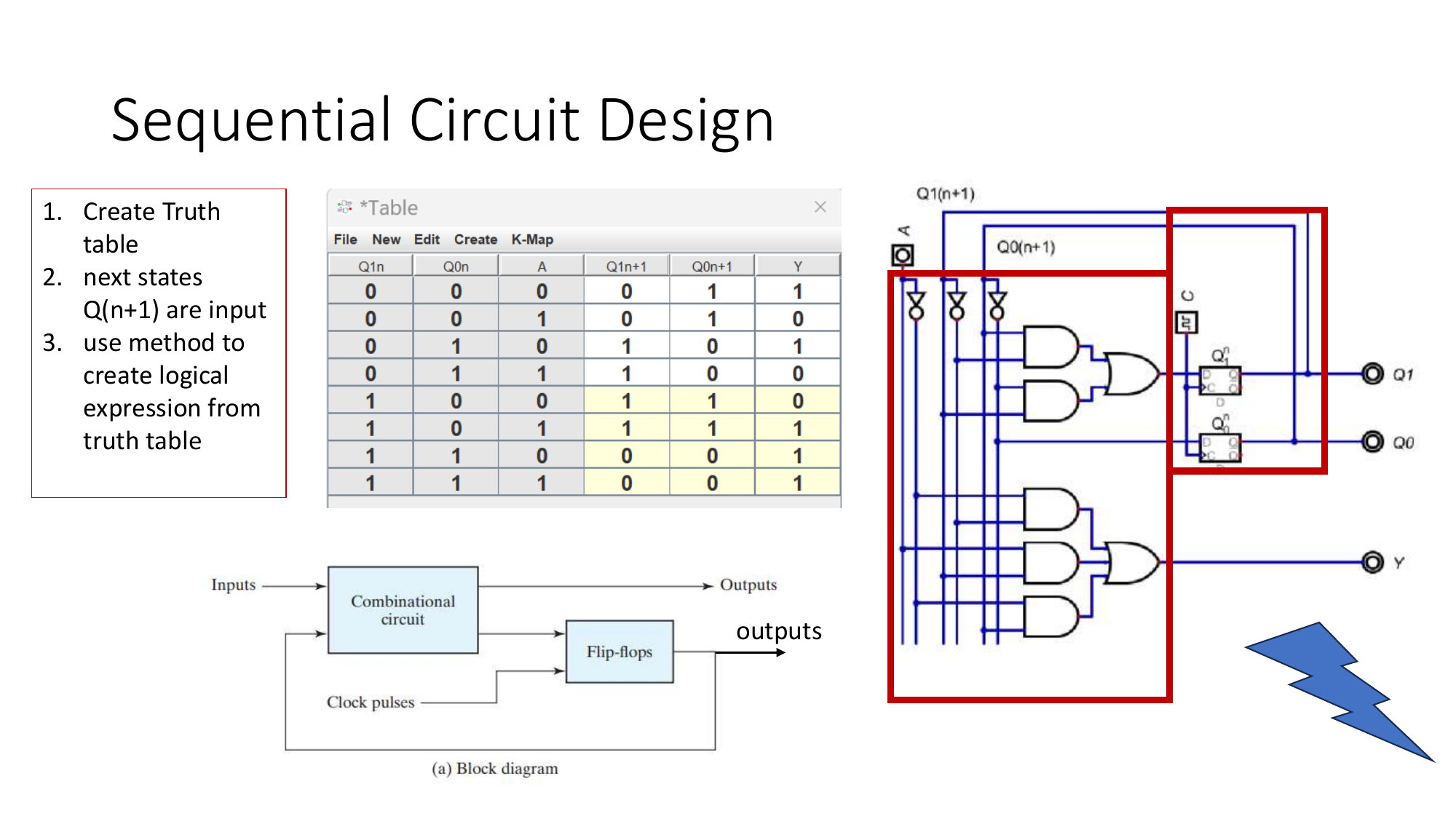
- Decide the states and draw the next-state truth table: columns are present state + inputs on the left, next state + outputs on the right.
- For each next-state bit, read its column as a function of the present-state and input columns.
- Minimise it (Karnaugh map) and that expression is the D input for that flip-flop.
- Wire the combinational logic to the D inputs, share one clock across all flip-flops, done.
It is the Week 4 design chain, with the present state added as inputs.
Worked example: a 2-bit counter
We want the state to step 00 → 01 → 10 → 11 → 00. Present state Q1 Q0, next state Q1+ Q0+:
| Q1 | Q0 | Q1+ | Q0+ |
|---|---|---|---|
| 0 | 0 | 0 | 1 |
| 0 | 1 | 1 | 0 |
| 1 | 0 | 1 | 1 |
| 1 | 1 | 0 | 0 |
Reading the columns: Q0+ = Q0' (it toggles every clock) and Q1+ = Q1 ⊕ Q0 (it toggles when
Q0 is 1). Those become the D inputs: D0 = Q0', D1 = Q1 ⊕ Q0.
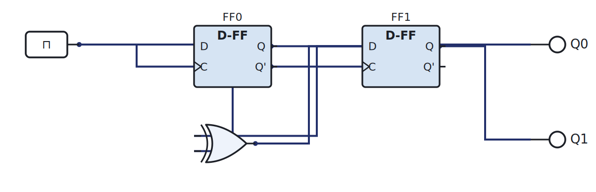
Step the clock and watch the two LEDs count in binary.
In the lab
The 2-bit counter is the course’s sequential lab. Build it in the simulator (Lab 3) and then on a breadboard with a dual D flip-flop IC clocked by the Arduino (Lab 4). Full instructions are in the Lab Annex.
Check yourself
- Write the next-state table for a counter that goes
00 → 10 → 01 → 11 → 00and find D0, D1. - Add an input
Upthat makes the 2-bit counter count down when it is 0. - Why does sharing one clock across both flip-flops matter?