Week 9: The first flip-flop
🏠 Home · Prev: Week 8 · Next: Week 10
Goal. Add memory. Everything so far has been combinational: the output depends only on the present inputs. A flip-flop remembers, and that is what turns logic into a machine with state.
The SR latch: the first bit of memory
Cross-couple two NOR gates, feeding each output back into the other’s input, and the circuit can hold a value. Set (S) forces the stored bit to 1, Reset (R) forces it to 0, and with both inputs 0 it remembers the last value.
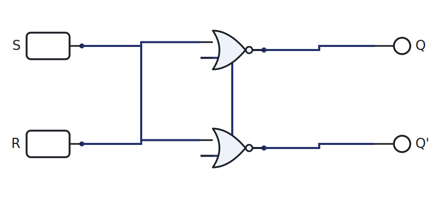
The combination S = R = 1 is forbidden, because it drives both outputs to the same value and the next state is ambiguous.
The problem with latches
A plain latch is transparent: while it is enabled, the output follows the input continuously, so any glitch on the input passes straight through, and feedback circuits can race.
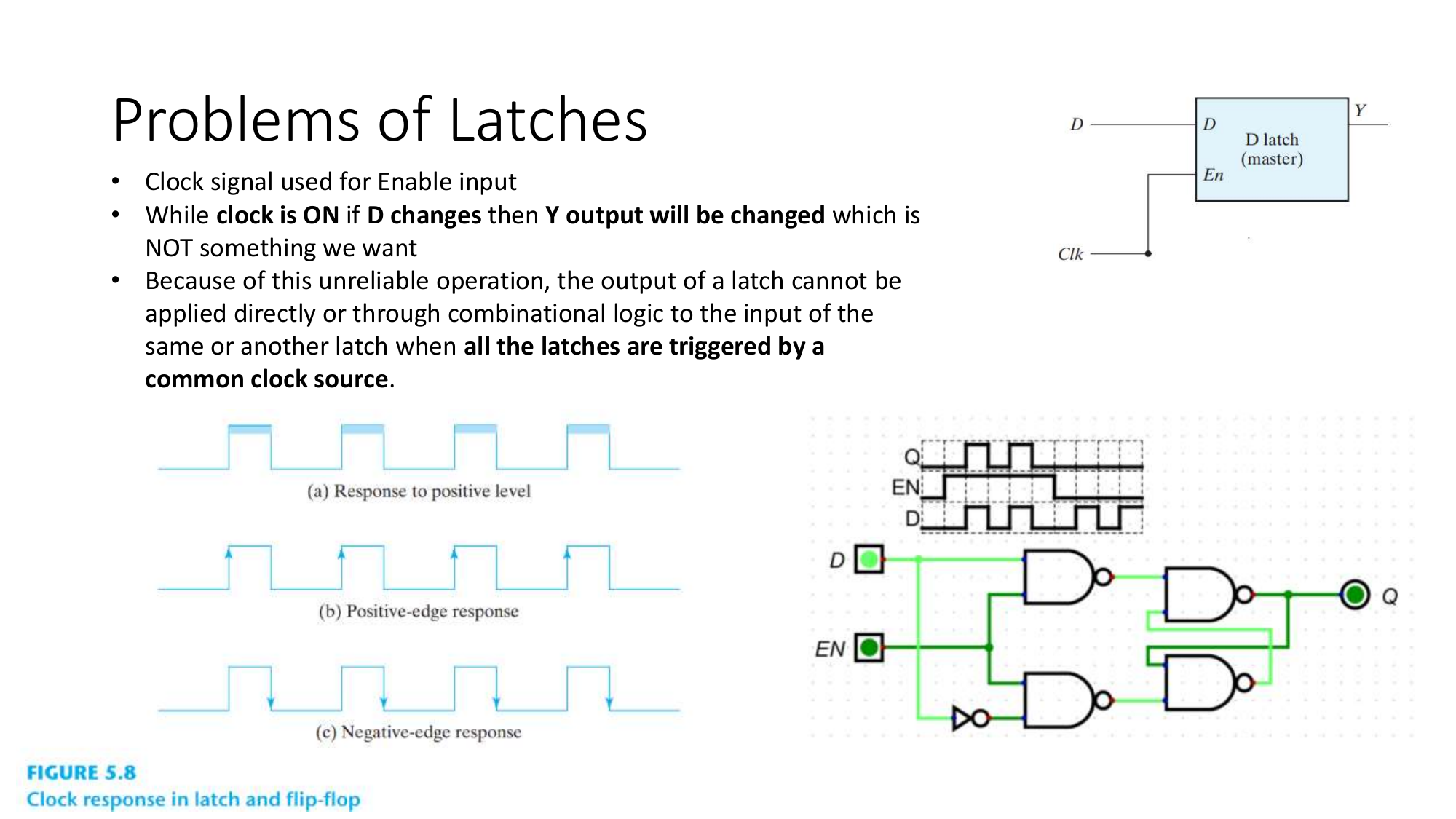
We want a circuit that samples its input at one instant, not for a whole interval.
The edge-triggered D flip-flop
The D flip-flop solves this: it copies D to Q only on the clock edge, and ignores D the rest of the time. One data input, one clock, and the stored bit changes once per clock tick.

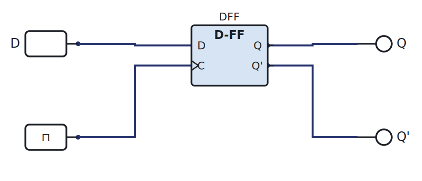
Open it, set D, and press the clock’s single-step button: Q takes D’s value on the edge and holds it until the next edge.
One flip-flop to rule them all
JK and T flip-flops exist, but we use the D flip-flop only. It is the simplest to reason about, and as the next week shows, it makes sequential design identical to the combinational design you already know.
Try it yourself (optional)
Build the SR latch from a NOR-gate IC, toggle S and R from the Arduino, and watch it hold. See the Lab Annex.
Check yourself
- Why is S = R = 1 forbidden on the NOR latch?
- What is the difference between “level-sensitive” and “edge-triggered”?
- On a rising-edge D flip-flop, D changes just after the edge. When does Q change?