Week 8: The MCU’s combinational blocks
🏠 Home · Prev: Week 7 · Next: Week 9
Goal. Finish combinational logic by building the remaining pieces that sit inside the microcontroller: the comparator, the decoder, the encoder, the multiplexer, and the lookup table. Each one is here because the MCU needs it.
Comparator
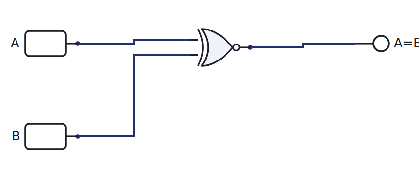
A comparator tells you whether two values are equal. For one bit, equality is XNOR: the output is 1 exactly when the bits match. For a wider word, XNOR each bit pair and AND the results together.
Decoder and demultiplexer
A decoder turns an n-bit address into one one-hot output: exactly one of its 2^n lines goes high, the one the address points at. In the MCU this is how an address selects a single ROM or RAM row, and how an instruction selects a single control action.
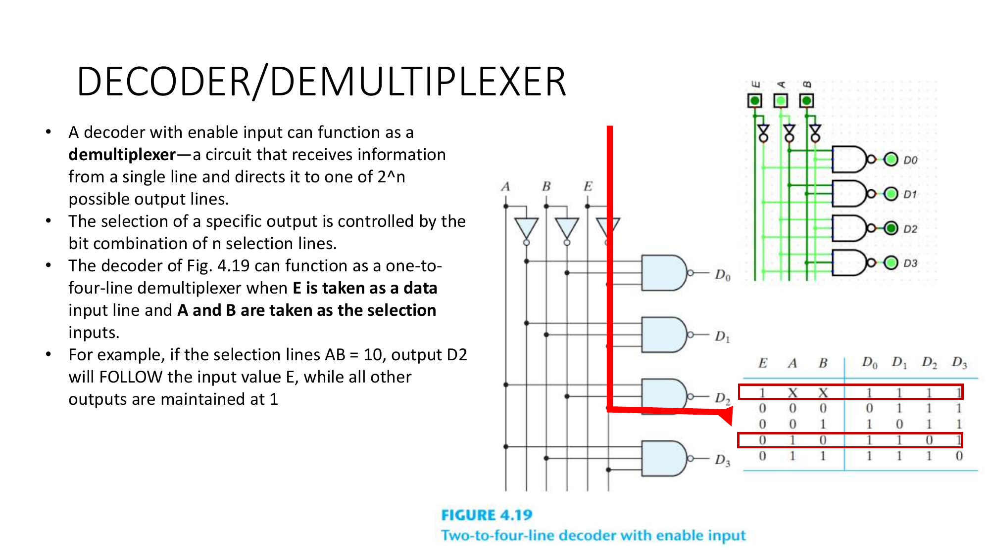
A demultiplexer is the same circuit with a data input gated onto the selected line.
Encoder
An encoder is the decoder run backwards: given one active input line, it outputs the binary number of that line. A priority encoder breaks ties by always reporting the highest active line, which is how interrupt hardware decides what to service first.
Multiplexer
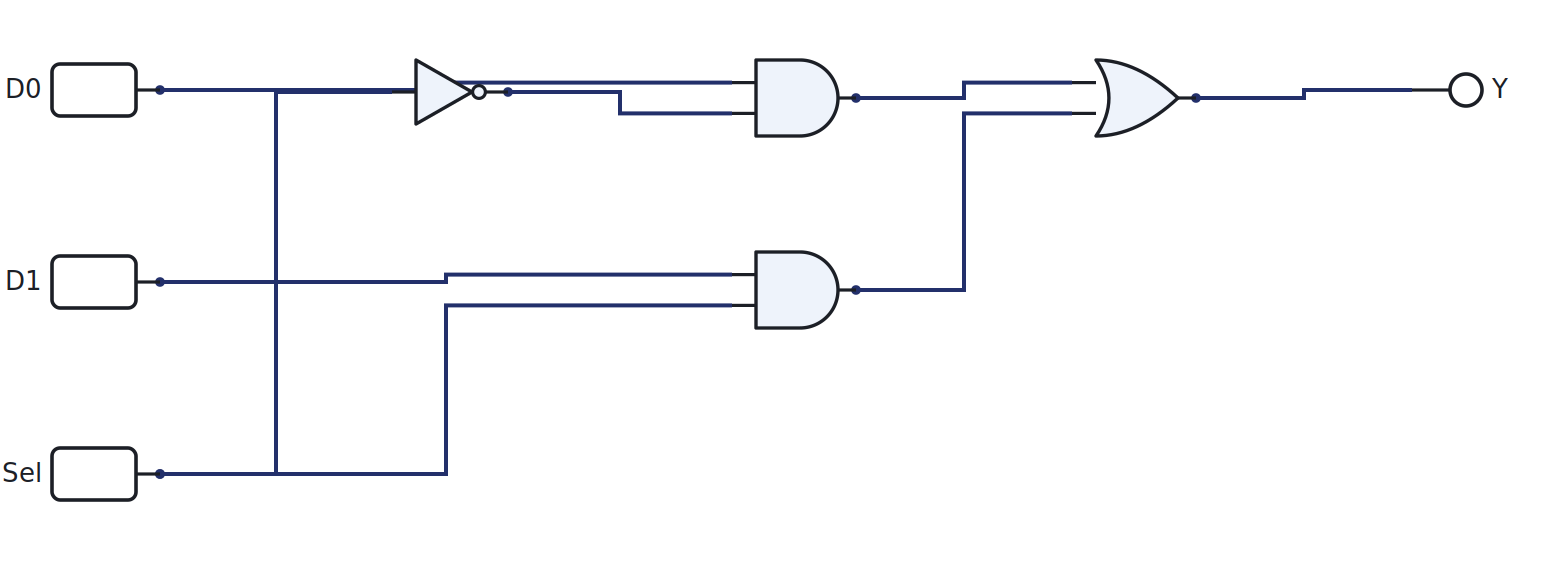
A multiplexer selects one of several inputs and passes it to the output, chosen by select
lines. A 2-to-1 MUX is Y = D0·Sel' + D1·Sel.
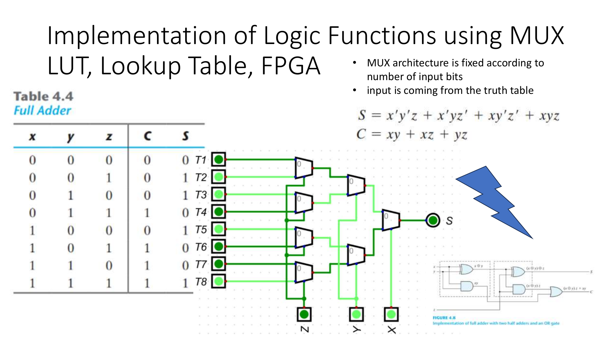
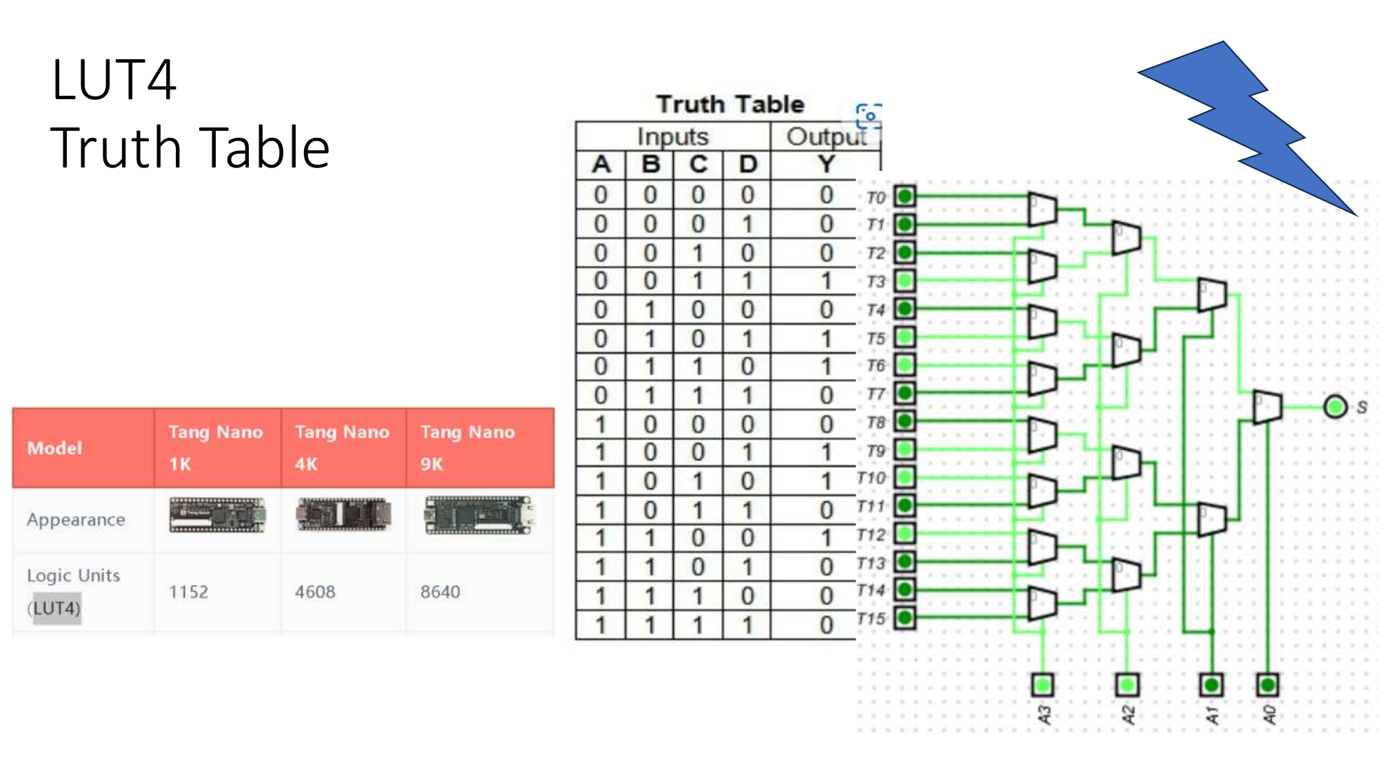
A MUX can also implement any logic function: wire the truth-table outputs to the data inputs and drive the select lines with the variables.
Lookup table (LUT)
Push that idea one step further and store the truth-table outputs in memory instead of wiring them. That is a lookup table, and it is the basic cell of an FPGA. LogicLab’s LUT4 holds a 16-row, 4-input table as a hex value.
Why these are the MCU’s blocks
The decoder picks instructions and memory rows, the multiplexer routes data between units, the comparator evaluates conditions, and the LUT is the bridge to programmable logic. Together with the ALU from Week 7, these are every combinational part the Week 14 MCU needs.
Try it yourself (optional)
Build the 2-to-1 MUX on the breadboard, drive the select line from the Arduino, and confirm it passes the chosen input. See the Lab Annex.
Check yourself
- Extend the 1-bit comparator to 2 bits. How many XNORs and what combines them?
- A 3-to-8 decoder has how many outputs, and how many are high at once?
- Use a 2-to-1 MUX to build a NOT gate. (Hint: tie the data inputs to constants.)