Week 3: Boolean algebra and the eight gates
🏠 Home · Prev: Week 2 · Next: Week 4
Goal. Meet the gates you build everything from, and the small amount of Boolean algebra you need to describe them. We stay practical: the algebra is here to talk about circuits, not to grind through proofs.
An algebra of 0 and 1
A Boolean variable takes only two values, 0 and 1. Claude Shannon showed in 1937 that a switching circuit obeys the same algebra, which is why we can design hardware by writing expressions. Every gate below is one operation in that algebra.
Huntington postulates (read once, then move on)
Boolean algebra rests on a short list of postulates: closure, an identity for each operation (0 for OR, 1 for AND), commutativity, distributivity, and a complement for every variable. We list them so you can read Shannon’s paper, where they do the heavy lifting. We will not use them to minimise circuits; that job belongs to Karnaugh maps in Week 5.
The theorems you actually use
A handful come up constantly: A + 0 = A, A · 1 = A, A + A' = 1, A · A' = 0, double
negation (A')' = A, and above all DeMorgan: (A · B)' = A' + B' and (A + B)' = A' · B'.
DeMorgan is what lets you turn any circuit into NANDs or NORs only.
Operator precedence
NOT binds tightest, then AND, then OR. So A + B · C means A + (B · C). Use parentheses when
in doubt.
The eight gates
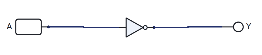
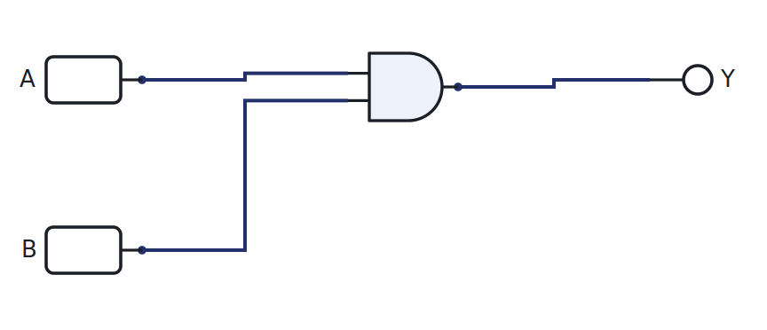
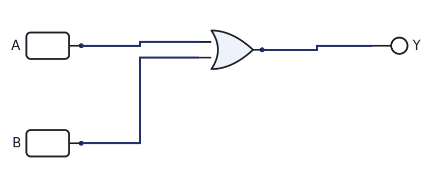
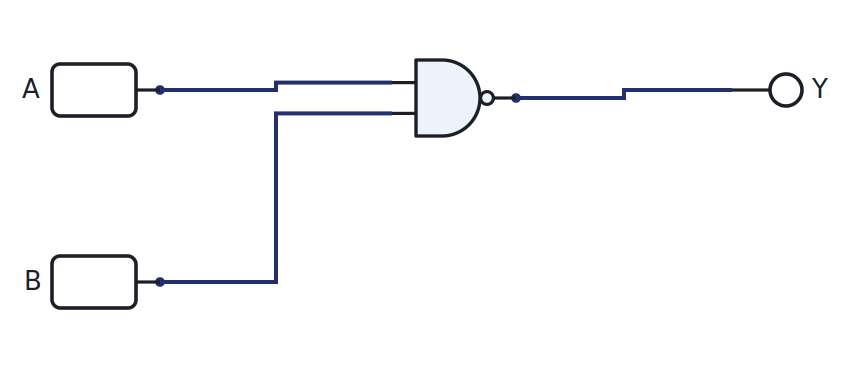
Each gate below is drawn in LogicLab, with its expression and truth table. Click Open in LogicLab to load the live circuit, then toggle A and B and watch Y.
NOT (inverter)
Y = A' — Inverts: output is the opposite of the input.
| A | Y |
|---|---|
| 0 | 1 |
| 1 | 0 |
AND
Y = A · B — Output is 1 only when both inputs are 1.
| A | B | Y |
|---|---|---|
| 0 | 0 | 0 |
| 0 | 1 | 0 |
| 1 | 0 | 0 |
| 1 | 1 | 1 |
OR
Y = A + B — Output is 1 when at least one input is 1.
| A | B | Y |
|---|---|---|
| 0 | 0 | 0 |
| 0 | 1 | 1 |
| 1 | 0 | 1 |
| 1 | 1 | 1 |
NAND
Y = (A · B)' — AND then invert. Universal: any circuit can be built from NANDs alone.
| A | B | Y |
|---|---|---|
| 0 | 0 | 1 |
| 0 | 1 | 1 |
| 1 | 0 | 1 |
| 1 | 1 | 0 |
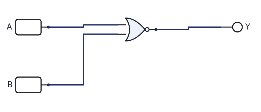
NOR
Y = (A + B)' — OR then invert. Universal as well.
| A | B | Y |
|---|---|---|
| 0 | 0 | 1 |
| 0 | 1 | 0 |
| 1 | 0 | 0 |
| 1 | 1 | 0 |
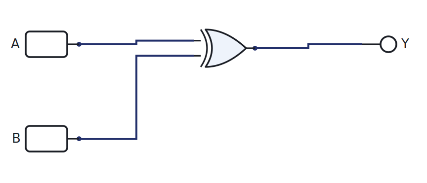
XOR (exclusive-OR)
Y = A ⊕ B — Output is 1 when the inputs differ. This is the adder’s sum bit.
| A | B | Y |
|---|---|---|
| 0 | 0 | 0 |
| 0 | 1 | 1 |
| 1 | 0 | 1 |
| 1 | 1 | 0 |
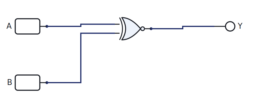
XNOR
Y = (A ⊕ B)' — Output is 1 when the inputs are equal. This is a 1-bit comparator.
| A | B | Y |
|---|---|---|
| 0 | 0 | 1 |
| 0 | 1 | 0 |
| 1 | 0 | 0 |
| 1 | 1 | 1 |
The eighth gate is the buffer: it just passes its input through, Y = A, used to
strengthen or delay a signal. In LogicLab a plain wire does the same job, so there is no separate
buffer part.
Multi-input gates
LogicLab’s gates take two inputs. A three-input AND is simply two AND gates in series:
A · B · C = (A · B) · C. Drawing the tree by hand is part of the lesson, and it is exactly how
you will wire it later.
Try it yourself (optional)
Pick one gate, wire it on the breadboard with a real gate IC, drive A and B from the Arduino (0 V and 5 V), and read Y back. Compare the bench result with the truth table and with LogicLab. See the Lab Annex for the wiring and code.
Check yourself
- Fill the truth table for
Y = (A + B)'from scratch, then confirm it against the NOR table. - Which two gates are universal, and why does that matter for manufacturing?
- Use DeMorgan to rewrite
A · Busing only an OR gate and inverters.