Week 2: From the real world to bits
🏠 Home · Prev: Week 1 · Next: Week 3
Goal. Logic works in 0 and 1, but the real world is decimal and analog. This week bridges the two: how we count in binary, what a 0 and a 1 actually are as voltages, and how a continuous signal becomes bits.
Decimal and binary
Decimal uses ten digits and powers of ten; binary uses two digits and powers of two. To read
binary, add the place values where there is a 1: 1101 is 8 + 4 + 0 + 1 = 13. To write a
decimal number in binary, subtract the largest power of two that fits and repeat, or divide by 2
and read the remainders from bottom to top. Two digits is all the hardware needs, because a wire
is either on or off.
What a 0 and a 1 really are
A logic 0 is not exactly 0 V and a logic 1 is not exactly 5 V. Each is a band of voltages. Anything below the low threshold counts as 0, anything above the high threshold counts as 1, and the gap between is undefined.
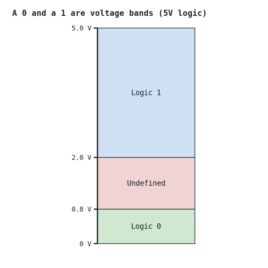
A gate drives its output well into the valid band (close to 0 V or close to 5 V) and only has to read an input as being on the correct side of a threshold. The slack between what a gate outputs and what the next gate needs to see is the noise margin, and it is why a little electrical noise does not corrupt the logic.
Cleaning a noisy edge: the Schmitt trigger
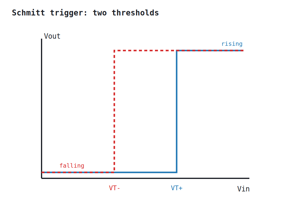
A slow or noisy signal crossing a single threshold wobbles across it many times, and the gate chatters. A Schmitt trigger fixes this with two thresholds: once the output switches, the input must travel all the way to the other threshold before it switches back. That gap is hysteresis, and it turns a messy, slow input into one clean edge.
From analog to digital: the ADC
Most real signals, a temperature, a microphone, a light sensor, are continuous voltages.
An analog-to-digital converter maps that voltage to the nearest of 2^n levels and
outputs the n-bit code for it. More bits means finer steps and more faithful numbers.
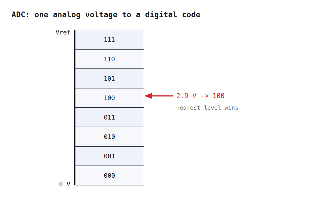
A 3-bit ADC over 0 to 5 V has 8 levels, so each step is about 0.6 V; a 10-bit ADC has 1024 levels and steps of about 5 mV. This is how the analog world enters a logic circuit as bits.
Try it yourself (optional)
The Arduino reads a continuous voltage with analogRead and a logic level with digitalRead,
which is exactly the ADC and the voltage-band ideas on the bench. The wiring and code are in the
Lab Annex.
Check yourself
- Convert 25 to binary, and convert
10110back to decimal. - Why must there be an undefined band between logic 0 and logic 1, rather than one sharp threshold?
- A 3-bit ADC over 0 to 5 V receives 3.2 V. Which code does it output?