Week 6: Binary arithmetic and the adder
🏠 Home · Prev: Week 5 · Next: Week 7
Goal. Build the circuit that adds. The adder is the heart of every ALU, so this is the first real piece of the microcontroller. This week is addition only; subtraction is next.
Adding in binary
Binary addition is the grade-school method with only two digits. Column by column you add the two bits and any carry coming in, write the sum bit, and pass a carry out to the next column. So the job splits into a small cell that adds three bits, repeated across the word.
The half adder
The half adder adds two bits and produces a sum and a carry. The sum is XOR (1 when the bits differ) and the carry is AND (1 only when both are 1).
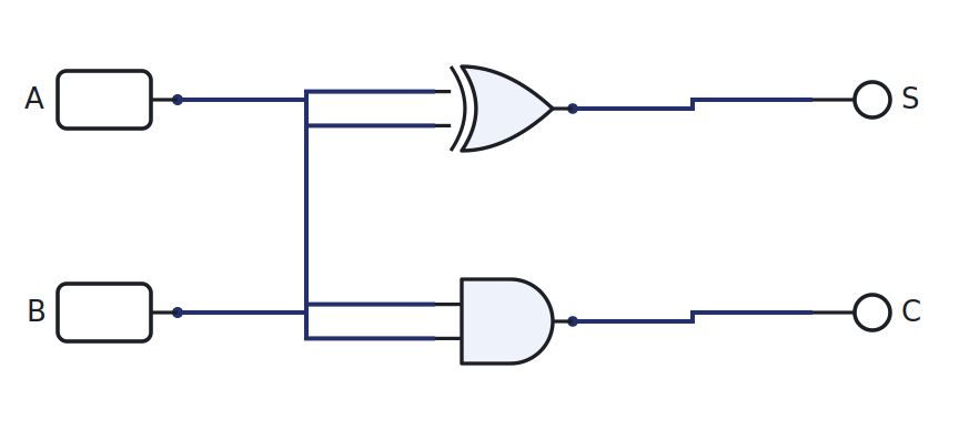
| A | B | C | S |
|---|---|---|---|
| 0 | 0 | 0 | 0 |
| 0 | 1 | 0 | 1 |
| 1 | 0 | 0 | 1 |
| 1 | 1 | 1 | 0 |
The full adder
A real column also has a carry in, so it adds three bits: A, B, and Cin. Build it from two half adders and an OR: one half adder adds A and B, the second adds that sum to Cin, and the OR combines the two carries.
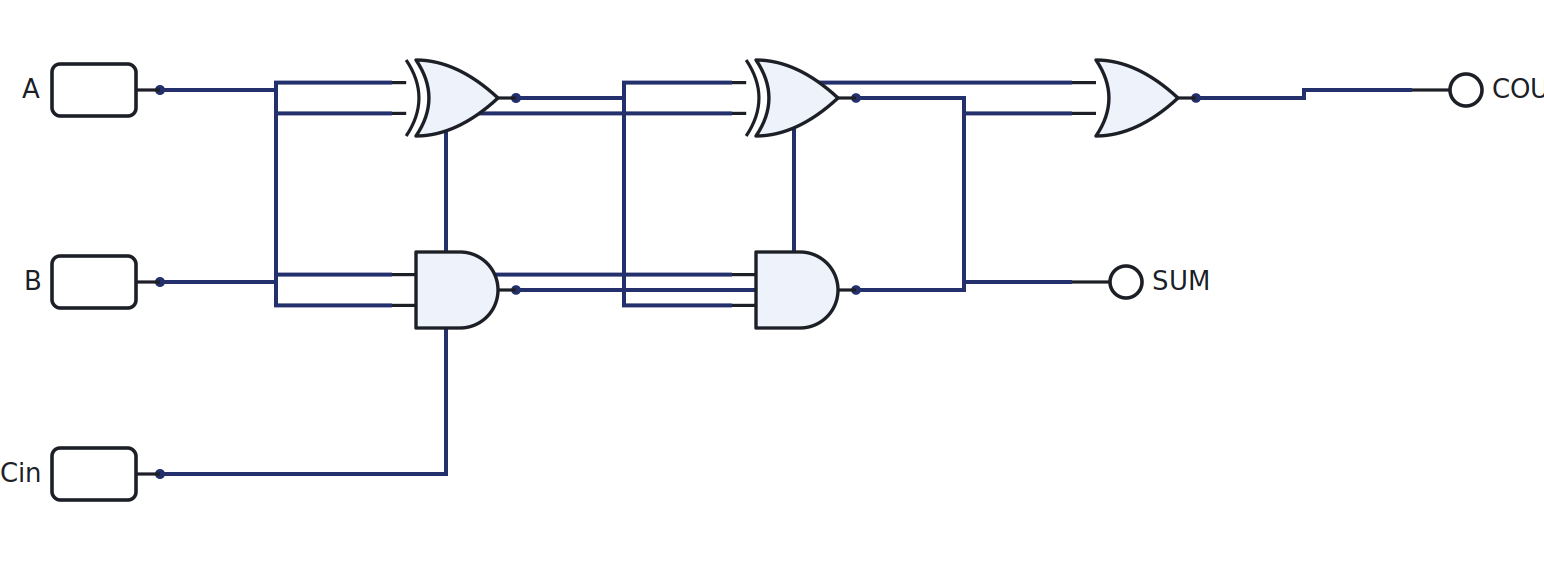
| A | B | Cin | Cout | S |
|---|---|---|---|---|
| 0 | 0 | 0 | 0 | 0 |
| 0 | 0 | 1 | 0 | 1 |
| 0 | 1 | 0 | 0 | 1 |
| 0 | 1 | 1 | 1 | 0 |
| 1 | 0 | 0 | 0 | 1 |
| 1 | 0 | 1 | 1 | 0 |
| 1 | 1 | 0 | 1 | 0 |
| 1 | 1 | 1 | 1 | 1 |
The 4-bit adder
Chain four full adders. Each one’s carry out feeds the next one’s carry in, so the carry ripples from the least significant bit up to the most significant.
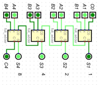
The full adder above is the single building block; the 4-bit adder is just four of them in a row.
Carry propagation, and why real adders are not a plain cascade
The cascade is easy to understand, but it has a cost. The top bit’s sum cannot settle until the carry has rippled all the way up from the bottom, so a 4-bit adder waits for four carry delays, an 8-bit adder for eight, and so on. The delay grows with the word length.
That is why a real adder IC is not just cascaded full adders. It uses carry-lookahead: extra logic computes the carries in parallel from the inputs, instead of waiting for them to ripple. So when you open an adder datasheet and the circuit looks more complicated than four full adders in a row, that is the reason, and it is no surprise.
Toward the ALU
The adder you built is the core of the arithmetic logic unit, the part of the MCU that computes. Next week we add one Mode line and turn this adder into an adder and subtractor, which is a basic ALU.
In the lab
The half adder is the course’s combinational lab. Build it in the simulator (Lab 1) and then on a breadboard with real XOR and AND ICs driven by the Arduino (Lab 2). Full instructions are in the Lab Annex.
Check yourself
- Fill the full-adder truth table from scratch, then confirm it in LogicLab.
- How many carry delays does a 16-bit ripple-carry adder take in the worst case?
- Add
1011 + 0110by hand, then check it on the 4-bit adder.