Week 11 — Finite State Machines: Mealy, Moore, Pattern Detection
The historical idea
Sequential building blocks (Weeks 8–9) plus combinational next-state logic (Weeks 6–7) combine into the most useful sequential abstraction: the finite state machine — a state register plus logic for the next state and the output. Pattern detection is the classic example.
Objectives
- Build an FSM as state register + next-state logic + output logic.
- Distinguish Moore (output = f(state)) from Mealy (output = f(state, input)).
- Implement the “BABA” detector (his example, inputs A/B/C/D as buttons).
- Verify exactly when the output fires, on the Console and waveform.
Concept (short)
An FSM has a finite set of states; transitions move between them on inputs; outputs are generated from the current state (Moore) or from state + input (Mealy). Mealy reacts in the same cycle as the input but can glitch; Moore is stable but lags by a cycle.
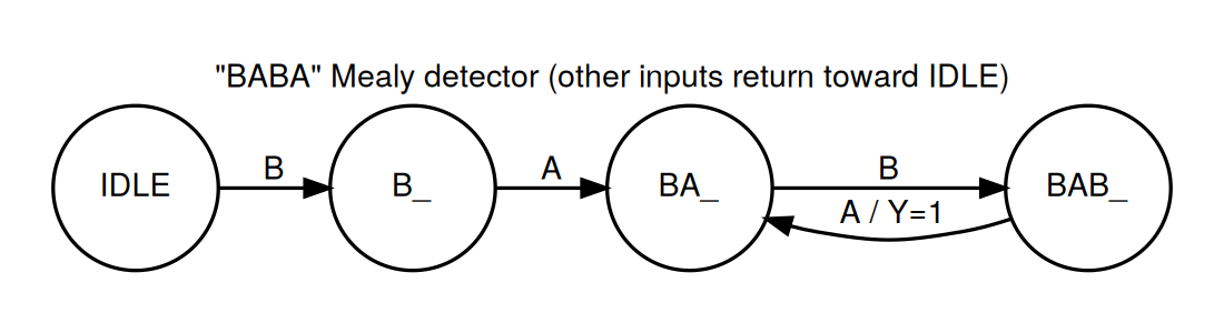
Example 1 — “BABA” detector (Mealy) — his example
Inputs A, B, C, D are four buttons (one-hot). Detect the sequence B → A → B → A. Output
Y=1the moment the fourth symbol completes. It is a Mealy machine becauseYdepends on being in stateBAB_and seeing inputA.
design.v
module sequence_detector(
    input clk, input rst,
    input A, input B, input C, input D,
    output reg Y
);
    localparam IDLE=2'd0, B_=2'd1, BA_=2'd2, BAB_=2'd3;
    reg [1:0] state, next;

    // state register (clocked)
    always @(posedge clk or posedge rst)
        if (rst) state <= IDLE;
        else     state <= next;

    // next-state + Mealy output (combinational)
    always @(*) begin
        next = state;
        Y = 1'b0;
        case (state)
            IDLE: if (B) next = B_;                       // got B
            B_:   if (A) next = BA_; else if (B) next = B_; else next = IDLE;
            BA_:  if (B) next = BAB_; else next = IDLE;    // got B A B
            BAB_: if (A) begin Y = 1'b1; next = BA_; end   // B A B A  -> detect! (overlap)
                  else if (B) next = B_; else next = IDLE;
        endcase
    end
endmodule
testbench.v
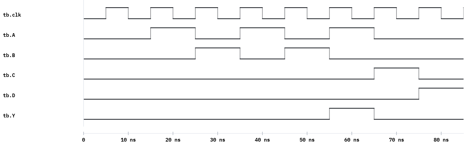
`timescale 1ns/1ns
module tb;
    reg clk=0, rst=1, A=0, B=0, C=0, D=0; wire Y;
    sequence_detector M0(.clk(clk),.rst(rst),.A(A),.B(B),.C(C),.D(D),.Y(Y));
    always #5 clk = ~clk;
    // Mealy: apply input, observe Y (combinational), THEN clock to register the transition
    task feed(input pa,pb,pc,pd);
        begin
            @(posedge clk);
            A=pa; B=pb; C=pc; D=pd;
            #1 $display("A=%b B=%b C=%b D=%b -> Y=%b", A,B,C,D, Y);
        end
    endtask
    initial begin
        $dumpfile("dump.vcd"); $dumpvars(0, tb);
        @(negedge clk) rst = 0;
        feed(1,0,0,0); // A  (ignored from IDLE)
        feed(0,1,0,0); // B
        feed(1,0,0,0); // A
        feed(0,1,0,0); // B
        feed(1,0,0,0); // A  -> BABA complete -> Y=1
        feed(0,0,1,0); // C
        feed(0,0,0,1); // D
        @(posedge clk) $finish;
    end
endmodule
Expected Console
A=1 B=0 C=0 D=0 -> Y=0
A=0 B=1 C=0 D=0 -> Y=0
A=1 B=0 C=0 D=0 -> Y=0
A=0 B=1 C=0 D=0 -> Y=0
A=1 B=0 C=0 D=0 -> Y=1
A=0 B=0 C=1 D=0 -> Y=0
A=0 B=0 C=0 D=1 -> Y=0
Y=1 appears exactly on the fifth input — the A that completes B-A-B-A (the leading A is
ignored from IDLE).
Why observe
Ybefore the clock edge? A Mealy output is combinational. Thefeedtask applies the input, waits#1for logic to settle, printsY, and then the next edge registers the state change. Sampling after the edge would miss the pulse.
Example 2 — Moore version of a detector (for comparison)
A Moore “1011” overlapping detector: the output depends only on state, so it is glitch-free and lags by one cycle.
design.v
module moore1011(input clk, input rst, input din, output detected);
    localparam S0=3'd0,S1=3'd1,S2=3'd2,S3=3'd3,S4=3'd4;
    reg [2:0] state;
    always @(posedge clk or posedge rst)
        if (rst) state <= S0;
        else case (state)
            S0: state <= din ? S1 : S0;
            S1: state <= din ? S1 : S2;
            S2: state <= din ? S3 : S0;
            S3: state <= din ? S4 : S2;
            S4: state <= din ? S1 : S2;
        endcase
    assign detected = (state == S4);   // Moore: from state only
endmodule
Feed 1011011 (bit0 first) and detection fires at bit#3 and the overlapping bit#6.
Example 3 — Toward hardware (preview of Week 13)
On the board, the BABA detector’s inputs map to buttons and Y to an LED, driven by a slow
clock so symbols can be pressed by hand. The FSM source is unchanged from simulation. We build
this in Week 13; note now which signals become buttons (A,B,C,D) and which an LED (Y).
Run it in VeriSim
- Run example 1; confirm
Y=1on the fifth input. - Synthesize → RTL: a small state register feeding combinational next-state/output logic — the textbook FSM block diagram from your code.
- Run example 2 and compare when it fires (Moore lags) versus the Mealy version.
What to look for
- Mealy vs Moore timing. Mealy
Ypulses in the same cycle as the triggering input; Mooredetectedreflects the state and is stable for a full cycle. The waveform shows both. - Overlap. Both detectors reuse a trailing symbol to start the next match.
Exercises (session 2)
- Trace by hand. For the BABA detector, write the state after each input of
B A B A B Aand mark everyY=1; verify against simulation. - Non-overlapping. Modify BABA so a detection resets fully to
IDLE(no overlap). Show the difference on a stream containingBABABA. - Moore BABA. Re-cast the BABA detector as a Moore machine (add a “detected” state) and compare the firing cycle with the Mealy version.