Week 10 — Synthesis: From Describing to Designing
The historical idea (the turning point)
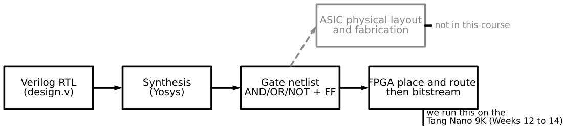
So far Verilog has done what it was invented to do: describe a hand-designed circuit and test it. The historical leap that made Verilog dominate: if a tool can read your description, it can also build the circuit. That is synthesis — Verilog → a gate-level netlist. In this course we follow the result up to the synthesized schematic; physical design (floorplanning, place & route, layout, fabrication) is mentioned but not performed.
Objectives
- State what synthesis does: source → gate/RTL netlist.
- Use VeriSim’s Synthesize to view Gates and RTL schematics.
- Read the difference: RTL keeps your hierarchy; Gates shows AND/OR/NOT.
- Identify what is synthesizable vs simulation-only.
Concept (short)
A synthesizer (VeriSim uses Yosys) converts RTL into primitive cells. The result may differ from what you expected but is logically equivalent. Two views:
- Gates — function in AND/OR/NOT only; matches the SOP/Karnaugh form, so an
xorappears decomposed. - RTL — higher view that keeps modules and shows registers/adders/muxes as blocks.
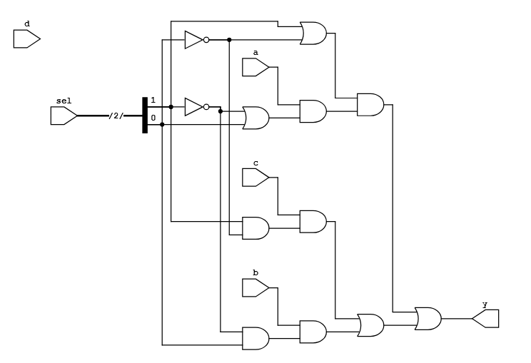
A concrete Gates view — the behavioral 4-to-1 mux from Week 7 (a case on sel) after
synthesis: sel drives inverters, each data input a/b/c/d passes through an AND gate
enabled by the decoded select lines, and an OR gate combines them into y. The case you wrote
is now pure AND/OR/NOT — logically identical, just lowered to primitives.
Synthesizable vs simulation-only
| Synthesizable (becomes hardware) | Simulation-only |
|---|---|
assign, always @(*), always @(posedge clk) |
initial blocks (use a reset instead) |
if-else, case, operators, vectors |
# delays (ignored by synthesis) |
| module instantiation, parameters | $display, $monitor, $dumpfile, $finish, $random |
Rule of thumb: describes circuit structure/behaviour → synthesizes; controls the simulation
→ does not. Incomplete always @(*) assignment → inferred latch.
Example 1 — See the full adder synthesized
Use the gate-level fulladder (or the dataflow one) from earlier weeks.
design.v — fulladder (Week 1).
Press Synthesize → Gates: the function in primitive gates. Press RTL: the higher-level view. Since the design is already gate-level, the two look similar — a good first, simple case.
Example 2 — Hierarchy preserved: the 4-bit adder
design.v — fulladder + fourbitadder (Week 4).
Synthesize → RTL: four fulladder blocks in a carry chain — your hierarchy, preserved.
Gates: the same function flattened into AND/OR/NOT. Same circuit, two zoom levels — this
answers “where did my modules go?”
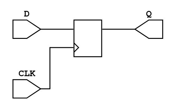
Example 3 — A flip-flop synthesizes; an initial block does not
design.v
// D flip-flop without reset
`timescale 1ns/1ps
module DFF(output reg Q, input D, CLK);
    always @(posedge CLK) Q <= D;     // synthesizes to ONE flip-flop
endmodule
Synthesize → RTL shows a single D flip-flop cell. Add a stray initial Q = 0; and note it
is a power-up value on an FPGA, not logic — it creates no gate.
Example 4 — The latch trap (and the fix)
design.v
module bad_mux(input [1:0] sel, input a, b, c, d, output reg y);
    always @(*)
        case (sel)
            2'b00: y = a;
            2'b01: y = b;
            2'b10: y = c;
            // 2'b11 missing, no default -> y must "remember" -> LATCH
        endcase
endmodule
Synthesize and read the latch warning. Add default: y = a; and the latch disappears.
Run it in VeriSim
- Synthesize examples 1 and 2; toggle RTL ↔ Gates and describe, in one sentence each, what changed (hierarchy kept vs dissolved).
- Synthesize example 3; find the single flip-flop in the RTL view.
- Synthesize example 4; observe the latch, then fix it with
default.
What to look for
- RTL vs Gates: RTL keeps modules; Gates is the technology-independent primitive form.
- The latch from an incomplete
caseis the most common synthesizable-code bug — catch it in the browser, not on the board. - Beyond the schematic comes physical design (place & route, layout) — the path to silicon (e.g. TinyTapeout). We stop at the schematic; the FPGA weeks map a synthesized design onto a real device.
Exercises (session 2)
- Style equivalence. Synthesize the half adder written three ways (gate, dataflow, behavioral); confirm the Gates view is the same function each time.
- Count the flip-flops. Synthesize a 4-bit counter and count flip-flops in the RTL view; relate to the bit width.
- Synthesizable audit. Take a module containing
#delayand$displayand rewrite it as synthesizable; list what you removed and why. - Multiplier surprise. Synthesize
assign p = a * b;for 4-bita,band inspect how much logic a single*produces.