Week 9 — Blocking vs Non-Blocking Assignments
The historical idea
Now that we have clocks, the kind of assignment inside an always block changes the
hardware. This is the most error-prone topic in Verilog, and the waveform is the only honest
way to see the difference.
Objectives
- Distinguish blocking
=from non-blocking<=. - Apply the rule: clocked logic →
<=, combinationalalways @(*)→=. - See the one-cycle pipeline non-blocking creates.
- Recognize the simulation/synthesis mismatch caused by the wrong choice.
Concept (short)
- Blocking
=executes immediately, in order; the next line sees the new value. - Non-blocking
<=samples all right-hand sides first, then updates together at the end of the step; every statement sees the old values — exactly how real flip-flops behave.
| Logic kind | Block | Assignment |
|---|---|---|
| Sequential (clocked) | always @(posedge clk) |
<= |
| Combinational | always @(*) |
= |
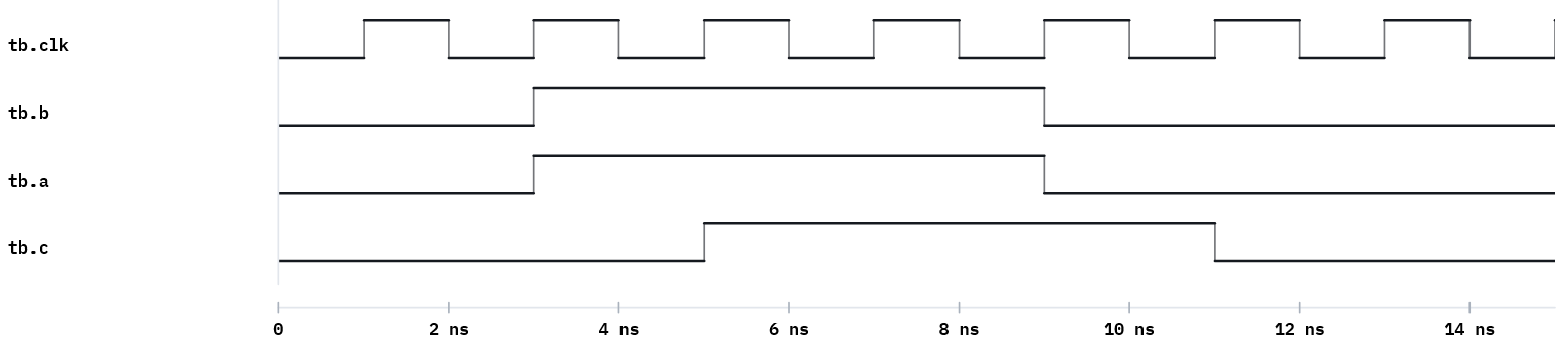
Example 1 — Non-blocking (his example): a <= b; c <= a;
design.v
`timescale 1ns/1ps
module nonblocking_example(
    input  wire clk,
    input  wire b,
    output reg  a,
    output reg  c
);
    initial begin a = 0; c = 0; end
    always @(posedge clk) begin
        a <= b;   // non-blocking
        c <= a;   // 'c' gets the OLD value of 'a' (before 'a' becomes 'b')
    end
endmodule
testbench.v
`timescale 1ns/1ps
module tb;
    reg clk, b; wire a, c;
    nonblocking_example DUT(.clk(clk), .b(b), .a(a), .c(c));
    initial begin clk = 0; forever #1 clk = ~clk; end
    initial begin
        $dumpfile("dump.vcd"); $dumpvars(0, tb);
        $monitor("t=%0t b=%b a=%b c=%b", $time, b, a, c);
        b=0; #3 b=1; #6 b=0; #6 $finish;
    end
endmodule
Expected Console
t=0 b=0 a=0 c=0
t=3 b=1 a=1 c=0
t=5 b=1 a=1 c=1
t=9 b=0 a=0 c=1
t=11 b=0 a=0 c=0
c lags a by one clock — a pipeline. When b becomes 1, a becomes 1 on the next edge,
and only on the following edge does c (which sampled the old a) become 1.
Example 2 — Blocking: a = b; c = a;
Same module, blocking assignment. Now c gets the new a in the same cycle.
design.v
`timescale 1ns/1ps
module blocking_example(
    input  wire clk,
    input  wire b,
    output reg  a,
    output reg  c
);
    initial begin a = 0; c = 0; end
    always @(posedge clk) begin
        a = b;   // blocking - immediate update
        c = a;   // 'c' gets the NEW value of 'a'
    end
endmodule
Run with the same testbench (rename the instance). a and c now move together — the
one-cycle pipeline of example 1 is gone.
Example 3 — The register-swap test
The cleanest demonstration of the difference.
design.v
module swap_nb(input clk, input [3:0] init_x, init_y, input load,
               output reg [3:0] x, y);
    always @(posedge clk) begin
        if (load) begin x <= init_x; y <= init_y; end
        else      begin x <= y;      y <= x;      end   // non-blocking: real swap
    end
endmodule
// Replace <= with = and x,y both become the same value (no swap).
Run it in VeriSim
- Run example 1, open the Waveform, stack
b,a,c. The one-cycle offset betweenaandcis the lesson — point at it. - Run example 2 and watch the offset disappear.
- Run example 3 with
<=(correct swap), then change to=and watch the swap break.
What to look for
- Non-blocking models “all flip-flops sample old values at the edge”; blocking models an
immediate sequential update — correct for combinational
always @(*), wrong for registers. - The swap (
x<=y; y<=x;) works with<=but not=. This single example settles the rule.
Exercises (session 2)
- Predict then verify. Before running, predict the
a/cwaveforms for both example 1 and example 2; then confirm. - Three-stage pipeline. Extend the non-blocking example to
a<=b; c<=a; d<=c;and count the cycles untildis stable. - Mixed mistake. In one clocked block, mix one
=and one<=on dependent signals and explain the surprising result from the waveform.