Week 4 — Hierarchical Modeling: Module in Module
The historical idea
Real circuits are built from smaller, already-tested blocks. Once your half adder and full adder pass their testbenches, you instantiate them inside bigger designs — “module in module.” This is the structural backbone of every large design.
Objectives
- Instantiate a sub-module inside another module (named ports).
- Build a full adder from two half adders.
- Build a 4-bit ripple-carry adder (
fourbitadder) from full adders. - Connect sub-modules with internal wires, including a carry chain.
- Verify a hierarchical design against a reference.
Concept (short)
submodule_name instance_name (.port(signal), .port(signal), ...);
Each instance is a copy of the sub-module; wires carry signals between instances. Reusing a verified block means you debug small, then compose.
Example 1 — Full adder from two half adders
design.v
module halfadder(output S, C, input A, B);
    xor G0 (S, A, B);
    and G1 (C, A, B);
endmodule

module fulladder(output S, Co, input A, B, Ci);
    wire W1, C1, C2;
    halfadder H0(.S(W1), .C(C1), .A(A),  .B(B));    // module in module
    halfadder H1(.S(S),  .C(C2), .A(W1), .B(Ci));
    or G4 (Co, C1, C2);
endmodule
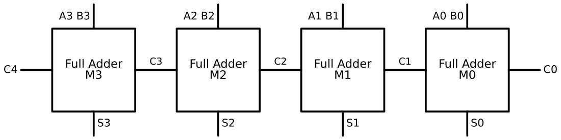
Example 2 — 4-bit ripple-carry adder (his fourbitadder)
design.v (uses the flat fulladder from Week 1)
// full adder
module fulladder(output S, Co, input A, B, Ci);
    wire W1, W2, W3;
    xor G0 (W1, A, B);
    xor G1 (S,  W1, Ci);
    and G2 (W2, A, B);
    and G3 (W3, Ci, W1);
    or  G4 (Co, W2, W3);
endmodule

// 4-bit ripple-carry adder
module fourbitadder(
    output S0, S1, S2, S3, C4,
    input  A0, A1, A2, A3, B0, B1, B2, B3, C0
);
    wire C1, C2, C3;
    fulladder M0(.S(S0), .Co(C1), .A(A0), .B(B0), .Ci(C0));
    fulladder M1(.S(S1), .Co(C2), .A(A1), .B(B1), .Ci(C1));
    fulladder M2(.S(S2), .Co(C3), .A(A2), .B(B2), .Ci(C2));
    fulladder M3(.S(S3), .Co(C4), .A(A3), .B(B3), .Ci(C3));
endmodule
testbench.v — check against the + reference
`timescale 1ns/1ns
module tb;
    reg  [3:0] A, B; reg C0;
    wire S0,S1,S2,S3,C4;
    integer i, errors = 0; reg [4:0] expect;
    fourbitadder M0(.S0(S0),.S1(S1),.S2(S2),.S3(S3),.C4(C4),
                    .A0(A[0]),.A1(A[1]),.A2(A[2]),.A3(A[3]),
                    .B0(B[0]),.B1(B[1]),.B2(B[2]),.B3(B[3]),.C0(C0));
    initial begin
        $dumpfile("dump.vcd"); $dumpvars(0, tb);
        for (i=0;i<20;i=i+1) begin
            A=$random; B=$random; C0=$random;
            #5 expect = A + B + C0;
            if ({C4,S3,S2,S1,S0} !== expect) begin
                $display("FAIL %0d+%0d+%0d=%0d", A,B,C0,expect); errors=errors+1; end
        end
        if (errors==0) $display("ALL %0d RANDOM TESTS PASSED", i);
        else           $display("%0d FAILED", errors);
        $finish;
    end
endmodule
Expected Console: ALL 20 RANDOM TESTS PASSED.
Example 3 — Hierarchy reuse: a 4-bit 2-to-1 MUX
Instantiate a 1-bit MUX four times to select between two 4-bit buses.
design.v
module mux2to1(output Y, input A, B, S);
    wire W1, W2, W3;
    not G3 (W1, S);
    and G1 (W2, A, W1);
    and G2 (W3, B, S);
    or  G4 (Y, W2, W3);
endmodule

module mux2to1_4bit(output [3:0] Y, input [3:0] A, B, input S);
    mux2to1 M0(.Y(Y[0]), .A(A[0]), .B(B[0]), .S(S));
    mux2to1 M1(.Y(Y[1]), .A(A[1]), .B(B[1]), .S(S));
    mux2to1 M2(.Y(Y[2]), .A(A[2]), .B(B[2]), .S(S));
    mux2to1 M3(.Y(Y[3]), .A(A[3]), .B(B[3]), .S(S));
endmodule
Run it in VeriSim
- Run example 1’s full adder with a self-checking testbench (Week 3’s pattern) — it should pass, confirming the two-half-adder construction.
- Run example 2 → ALL 20 RANDOM TESTS PASSED.
- Run example 3 and confirm
YfollowsAwhenS=0andBwhenS=1, bit-for-bit.
What to look for
- The carry chain
C0 → C1 → C2 → C3 → C4is the only wiring linking the four stages. Trace it; it is also why ripple-carry is slow (Week 5). - If
fourbitadderfails butfulladderpassed, the bug is in the wiring, not the block.
Exercises (session 2)
- 8-bit adder. Instantiate two
fourbitadders, chainingC4 → C0. Verify against+. - Subtractor. Feed
~BandC0=1(two’s complement) to getA − B. Confirm. - Name the bug. Connect
M2’sCitoC1instead ofC2; predict which sums break and verify. - 4-to-1 from 2-to-1. Build a 4-bit 4-to-1 MUX by composing your
mux2to1_4bitblocks.