Week 2 — Testbenches: How Do We Test the Circuit We Described?
The historical idea
We described a circuit last week. Verilog’s reason for existing is the next question: how do we test it? A testbench is a Verilog module that creates inputs, feeds the circuit through an instantiation, and lets us observe outputs in the Console and as a waveform.
Objectives
- Structure a testbench: stimulus (
reg), observation (wire), and the instantiated DUT. - Use named instantiation
M0(.S(s), .C(c), .A(a), .B(b)). - Use
$display,$monitor,$dumpfile/$dumpvars,$finish. - Read
`timescaleand#delays (precision is detailed in Week 8).
Concept (short)
A testbench has no ports — it is the top of the simulation. Inputs are reg (you drive
them); outputs are wire (the DUT drives them). The waveform appears only if you dump it.
| Task | Meaning |
|---|---|
$display(...) |
print once, now |
$monitor(...) |
print automatically whenever a listed signal changes |
$dumpfile/$dumpvars |
record signals for the Waveform tab |
$finish |
stop the simulation |
Example 1 — Testbench for the half adder
Compact monitor format ab:cs, the style from the slides.
design.v
module halfadder(output S, C, input A, B);
    xor G0 (S, A, B);
    and G1 (C, A, B);
endmodule
testbench.v
`timescale 1ns/1ns
module tb;
    reg  a, b;          // reg for inputs
    wire s, c;          // wire for outputs
    halfadder M0(.S(s), .C(c), .A(a), .B(b));
    initial begin
        $dumpfile("dump.vcd"); $dumpvars(0, tb);
        $display("ab:cs");
        $monitor("%b%b:%b%b", a, b, c, s);
        a=0; b=0; #10;
        a=0; b=1; #10;
        a=1; b=0; #10;
        a=1; b=1; #10;
        $finish;
    end
endmodule
Expected Console
ab:cs
00:00
01:00
10:00
11:10
(Reading cs: the carry is high only for 11.)
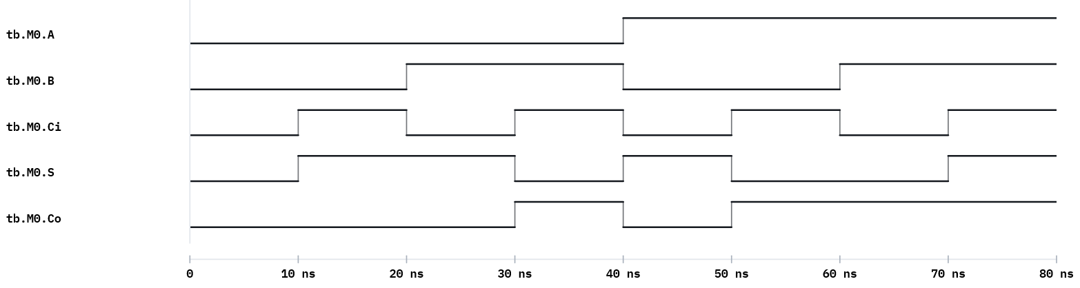
Example 2 — Testbench for the full adder
Loop over all 8 input combinations with a 3-bit counter.
design.v — fulladder from Week 1.
testbench.v
`timescale 1ns/1ns
module tb;
    reg  [2:0] in;             // {A, B, Ci}
    wire S, Co;
    integer i;
    fulladder M0(.S(S), .Co(Co), .A(in[2]), .B(in[1]), .Ci(in[0]));
    initial begin
        $dumpfile("dump.vcd"); $dumpvars(0, tb);
        $display("A B Ci : Co S");
        for (i = 0; i < 8; i = i + 1) begin
            in = i; #10;
            $display("%b %b  %b :  %b %b", in[2], in[1], in[0], Co, S);
        end
        $finish;
    end
endmodule
Expected Console
A B Ci : Co S
0 0  0 :  0 0
0 0  1 :  0 1
0 1  0 :  0 1
0 1  1 :  1 0
1 0  0 :  0 1
1 0  1 :  1 0
1 1  0 :  1 0
1 1  1 :  1 1
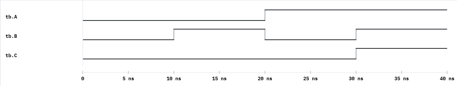
Example 3 — Testbench for the 2-to-1 MUX
Drive data and select; watch the output follow the chosen input.
design.v — mux2to1 from Week 1 (gate-level), or any equivalent.
testbench.v
`timescale 1ns/1ns
module tb;
    reg  a, b, s;
    wire y;
    mux2to1 M0(.Y(y), .A(a), .B(b), .S(s));
    initial begin
        $dumpfile("dump.vcd"); $dumpvars(0, tb);
        $display("a b:s y");
        $monitor("%b %b:%b %b", a, b, s, y);
        a=0; b=1; s=0; #10;   // s=0 -> y follows a
        s=1;             #10;  // s=1 -> y follows b
        a=1; b=0; s=0;   #10;
        s=1;             #10;
        $finish;
    end
endmodule
Run it in VeriSim
- Run example 1. The Console shows the header then one line per change (that is
$monitor). - Replace
$monitorwith a$displayinside each step. Notice:$displayprints exactly when called;$monitorprints whenever a signal changes. - Open the Waveform and confirm the carry/output behaviour visually.
What to look for
regfor inputs,wirefor outputs — getting this backwards is the most common first error.- The instance name (
M0) and dotted ports are the exam-standard form. $dumpvars(0, tb)uses the testbench module name. Rename the module → update the dump call.
Exercises (session 2)
- MUX from your testbench. Write a self-driving testbench for your Week-1
mux2to1that checks all four(a,b)for bothsvalues; format the output asa b:sel y. - Decoder testbench. Write a testbench for the 2-to-4 decoder that prints
Y3 Y2 Y1 Y0for each address, withG=1, then once withG=0. - Timing read. Insert a
#15somewhere and predict the exact$timeof every following line before running; confirm against the Console. - No
$finish. Remove$finish, run, and explain what happens and why it matters.